How to Program a CNC Lathe – A Complete Guide
CNC lathe programming will allow you to run precision cutting, carving, and drilling operations.
As a matter of fact, programming CNC lathe requires experience and expertise. This is because you must be familiar with operating CNC machine and the codes.
In this guide, we shall explore a detailed and practical approach on CNC lathe machine programming process.
Take a look:
Understanding CNC Lathe Programming
CNC lathe programming is the writing of code, which keeps the machine informed about how to make cuts, turnings as well as shapes to your workpiece. For this, G-codesand M-codes are used to describe the movement, speed, and tool change functionality in use on the machine.
Ideally, all these falls under a broad subject called, numerical control.
Preparing for CNC Lathe Programming
1. Selecting the Right CNC Lathe Machine
It is for your CNC machining needs that you should select the right CNC lathe. There are different types of CNC lathes like horizontal CNC, vertical CNC, and Swiss CNC types, offering various advantages. A Swiss type lathe is perfect for achieving precision for small, complex parts.
On the other hand, horizontal lathes support and stabilize larger components better. Your choice would also depend on varying aspects like spindle power, tool capacity, and automated features. Thus, meeting production requirements ensure that you avoid inefficiencies and costly errors with your machine.
2. Know Workpiece Specifications
Programming any CNC lathe requires certain preliminaries, including knowledge concerning materials as well as dimensions, especially on the workpiece. You should note, for instance, that the cutting parameters differ between metals such as aluminum, steel and titanium compared to polymers or composites.
Further, each of the given materials reacts to both heat and pressure differently, thereby affecting feed rate and even tool selection. Failure to take into consideration these aspects results in wrong cuts, too much waste, or tool destruction.
3. Selecting the Right Tools for Cutting
Regarding precision, tool life, and efficiency, the most crucial factor for choosing a cutting tool is cutting tool selection. Select tool holder and insert that are appropriate to the workpiece material and the type of machining process involved.
Carbide inserts are better suited for high speed cutting and high speed steel tools will work better in the slower cutting speeds because they are generally more flexible.
The tool geometry-in particular, rake angles and the chip breaker also play a role in surface finish and chip evacuation. Thus, using the correct tools reduces wear, reduces downtime, and contributes to overall performance in machining.
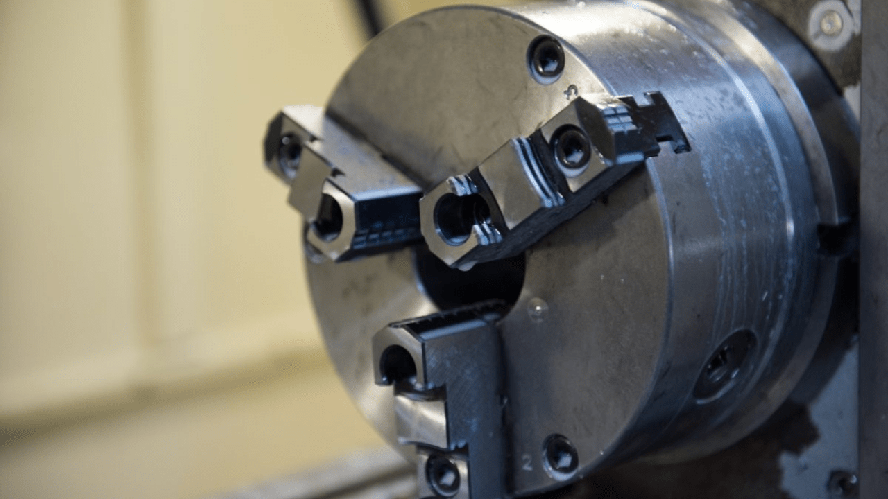
4. Workholding and Fixturing Methods
The way you secure the workpiece should prevent motion during machining and thus promote accuracy. Workholding includes chucks, collets, and faceplates, among others, which work best with different parts.
A three-jaw chuck is suitable for the general holding of round workpieces, while, collet offers higher precision for smaller parts. On the other hand, faceplates will secure odd-shaped workpieces.
Therefore, good workholding decreases vibration, holds the workpiece steady, and prevents misalignment while machining. If the workpiece is not properly secured, it will result in inaccuracy or damage to the machine.
Setting up the CNC Lathe
· Powering Up and Initializing the Machine
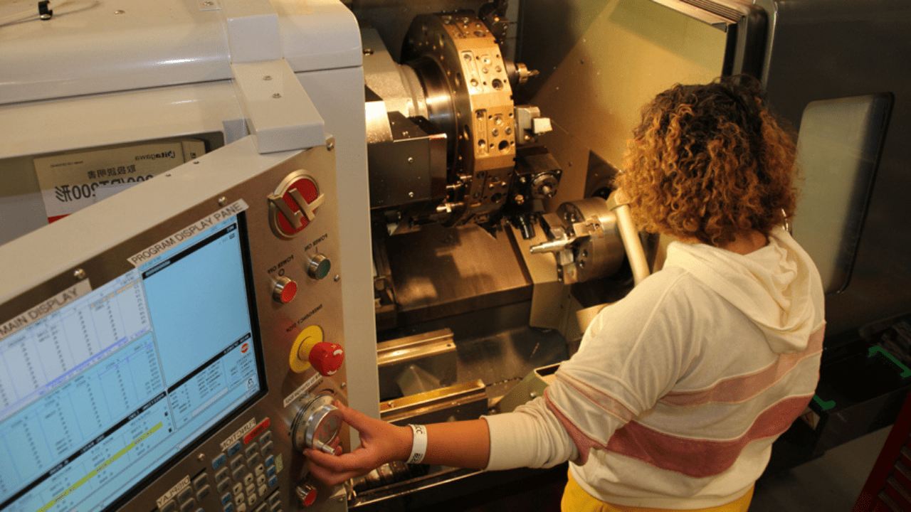
The very first step toward programming and cutting on a CNC lathe is to turn on the machine. On switching on the machine, the control system runs through a self-diagnostic to check that everything is functioning correctly.
For example, the homing process is the one that moves the machine to a reference position, resetting the axis and preparing for precise movement. Skipping this process may lead to misalignment or erroneous positioning of the tool. With the control panel, you can then check system settings, offsets of the tools, and parameters of the spindle before starting the machining operation.
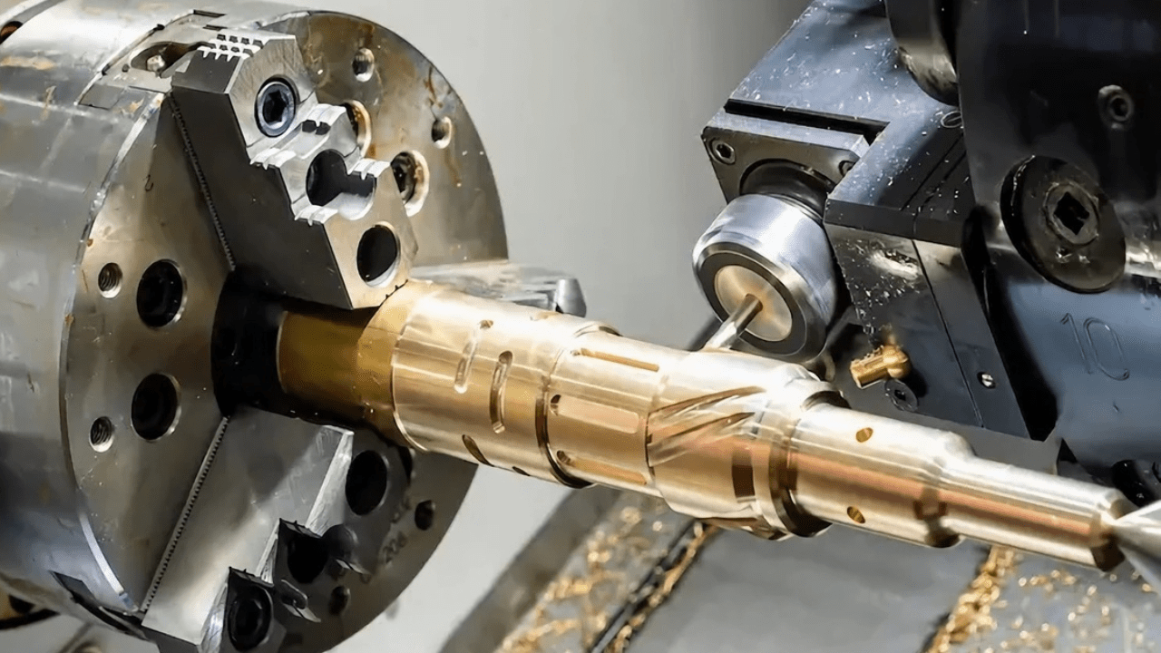
· Loading the Workpiece and Securing It Properly
Good positioning of the workpiece is required for precision machining. Depending on the shape, size, and type of material of the workpiece, a workholding method is selected.
For instance, you will use a three-jaw chuck to machine round parts but need a four-jaw chuck to secure irregular shapes to allow more accurate alignment. For small parts, however, a collet chuck grips them suitably without applying so much pressure. Thus, good alignment prevents vibration, which is essential to ensure smooth and precise cutting.
Furthermore, clamping forces must be balanced to prevent deformation of a workpiece. Excessive clamping can lead to crushing of the workpiece, whereas insufficient clamping may allow the workpiece to slip.
Therefore, you should test the lathe by manually rotating the spindle to see if the workpiece holds firmly. If any movement or wobble is noticed in the workpiece, adjustment must be made to avoid machining errors. Thus, proper clamping means less chance of tool breakage and greater dimensional accuracy during the process.
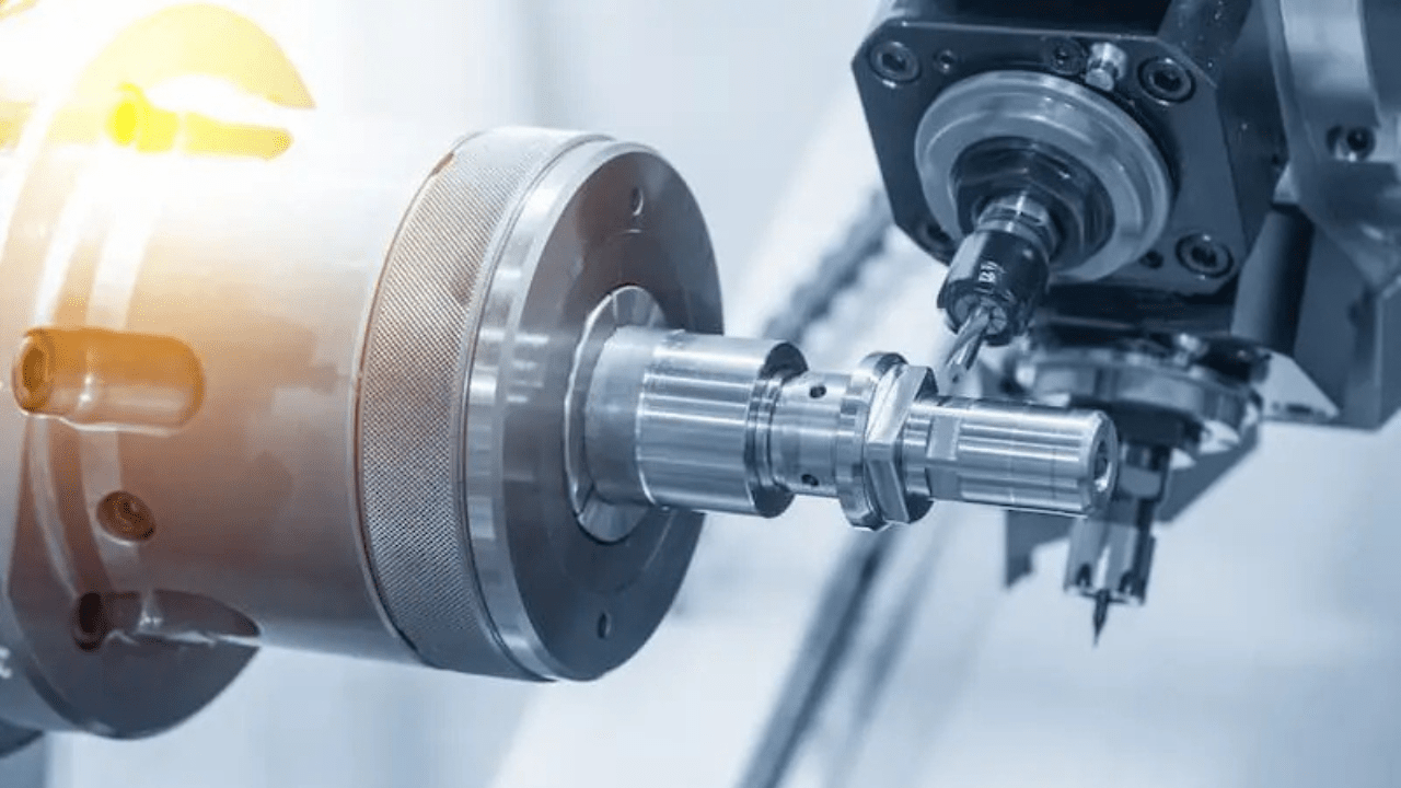
· Tool Selection and Tool Offset Setup
The choice of the right tool for work determines cutting efficiency and surface finish. There are various tools that perform different operation like roughing, drilling, finishing, and tapping.
Carbide inserts, for example, are very durable, and therefore suitable for the high-speed cutting of metals, and high-speed steels are more flexible for the softer materials.
On the other hand, toolholders are necessary for stability and deflection minimization. Thus, a rigid tool-set up allows for very little chatter, enhancing tool life and enabling reproducible results.
Additionally, tool offsets are used for precision cutting. Each tool has a separate offset used to define the exact position of that tool with respect to the workpiece. Without entering these values correctly in the CNC control, the correct depth of cut can not be ensured, and collisions can occur.
Some machines provide automatic tool measurement using a probe, while others require manual entry. Checking the tool offset before commencing any machining operation helps eliminate costly mistakes and maintain part quality.
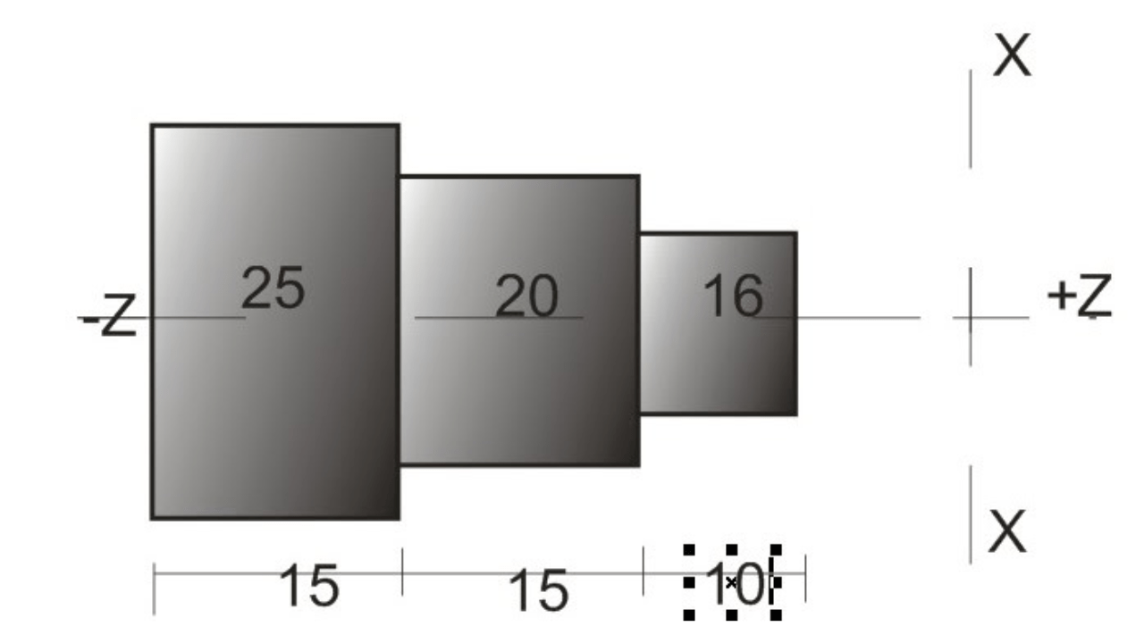
· Setting the Workpiece Zero Point
Zeroing means that the CNC lathe can run all programmed commands accurately. This is the reference for the machine to start cutting. Since most lathes now adopt a work offset system like G54 to G59, different zero positions can be defined for several setups.
It is important because if that point is not set properly the tool would cut in the wrong place and damage the workpiece or equipment.
Commonly, the zero point may be defined using a touch-off tool or edge finder. On some CNC lathes, automatic probing systems set this position accurately. Once the zero point is set, all tool paths are measured from this reference.
Failure to do this will lead to incorrectly measured parts and wasted material. Accurate setting of the zero reference ensures the part is correctly aligned and avoids errors during machining.
· Speed of Spindle and Feed Rate Calculations
Spindle speed is the speed at which the cutting tool rotates while feed rate corresponds to how fast the cutter moves into the material. You should carefully set these two parameters for efficient material removal without wear on the tool.
Moreover, the ideal range varies as per the workpiece material, tool type, and required surface finish. Lower speeds are needed for harder materials and higher speeds can be tolerated for softer materials, without heat buildup.
Feed rate also influences cutting efficiency and chip formation. Thus, a slow feed rate will ensure a smooth finish but may also rub the tool, thereby decreasing its life.

Writing the CNC Lathe Program
1. Program Format and Structure
CNC programs require a prescribed format. Each line consists of G-codes (movement commands) and M-codes (machine commands). Good formatting ensures there are no errors and smooth execution.
2. Comments and Documentation
Programming in the form of comments allows the programmer to understand code later on. For example, “TOOL CHANGE FOR ROUGH CUTTING” is describing what this command is used for. Well-documented programs decrease the chance of confusion and are indispensable for error detection.
3. Important CNC G-Codes and M-Codes
G-Codes used in Turning Operations (G00, G01, G02, G03)
- G00 – Rapid movement (non-cutting motion)
- G01 – Straight-line cutting at a controlled feed
- G02 – Clockwise arc cutting
- G03 – Counterclockwise arc cutting
Tool Movement and Positioning
- G90 (Absolute Positioning): Movements are based on zero point reference.
- G91 (Incremental Positioning): Movements are based on the previous position.
Spindle Control and Tool Change Commands (M03, M04, M06)
- M03 – Spindle ON (clockwise)
- M04 – Spindle ON (counterclockwise)
- M06 – Tool change
Creating a Basic CNC Lathe Program
1. Initial Setup Commands
Before machining can commence, you must effect proper setup for smooth operations. The program starts with preparatory commands that set the machine for the operation.
G21, for example, is used to set metric measurements, whereas G20 is for inch measurements to avoid conversion errors.
The work coordinate system must also be established using either the G54, G55, or other offsets. This determines the position of the workpiece so that accurate movements can be carried out.
Proper spindle activation and tool selection is also included in the setup. M03 command activates the spindle in a clockwise direction, whereas, M04 operates it counterclockwise. You should assign spindle speed by the S command as per the requirements of the material cut.
Moreover, selection for the proper tool using T and M06 will cause the machine to load the right cutter. Those commands are building blocks for an orderly and efficient machining process, without which the machine would simply fail to know how to operate properly.
2. Roughing Pass and Finishing Pass Commands
Roughing operations are intended to get rid of excess matter rapidly and efficiently. Commands like G00 for rapid positioning and G01 for controlled linear movements are applied in guiding the tool throughout the first cutting operation.
You need the F command to specify an appropriate feed rate in consideration of speed versus cutting forces.
Therefore, roughing passes generally involve several depth increments for minimizing stress on the tool and preventing buildup of excess heat.
3. Drilling, Threading, Grooving Operations
For drilling, it is necessary to have accurate positioning and depth control to make holes accurately. The simple drilling cycle is activated by G81, while peck drilling is performed with G83.
Additionally, you must indicate spindle speed, the feed rate, and depth for the prevention of tool breakage. A combination of a correct drill size and proper use of coolants can help keep the hole quality and tool life at its best.
Thus, inadequate strategy in drilling results in the build-up of chips, deflection of tools, and variations in hole diameters.
Threading synchronizes spindle rotation as well as tool movement. G76 and G92 set commands for making exact external or internal threads. To avoid tear of the material and undue wear in the tool, you have to control the cutting depth.
For the grooving operations, the tools are also used to cut recesses or channels in the workpiece. Tools are put under less stress, and chip removal is made easier with G75 command peck grooving.
4. Using Subprograms and Loops
Subprograms ease the programming task for repetitive machining processes. For example, M98 commands call a subprogram so that pre-fed cutting sequences can be reused. It saves time and reduces the possibility of error in programming.
In the case of machining multiple identical parts, subprograms ensure that the same code will be applied with no code rewriting. Neglecting the use of subprograms almost always results in long programs that become more and more difficult to debug and modify.
Furthermore, loops simplify the optimization of tool movements by providing the ability to repeat certain commands. For example, the M99 command permits the means of looping any subprogram used in production. Loops can be employed for repetitive operations such as drilling holes, threading, or contouring.
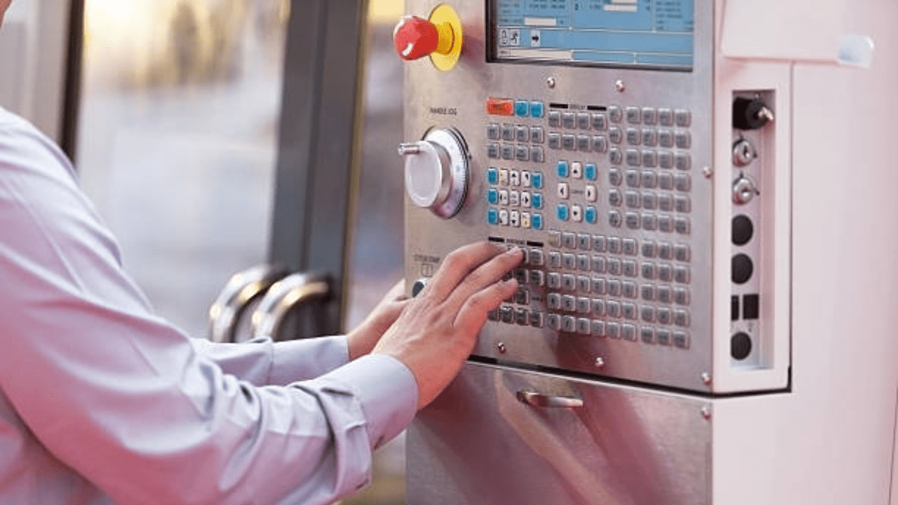
Inputting and Simulating the Program
1. Transferring the Program to the CNC Lathe
You still have to transfer the program to the machine once you have completed writing the CNC lathe program. The use of USB drives, Direct Numerical Control, or direct typing via the control panel are common transfer methods in most CNC lathes.
The simplest and fastest way to upload programs for stand-alone machines is through USB transfers. Direct Numerical Control links the CNC lathe to a computer and allows data to be transferred in real time.
On the other hand, manually inputting the code requires careful keystrokes to avoid making any mistakes, but a small change can be made directly on the machine. Most of these transfer methods are up to your workflow, capabilities of the machine, and the requirements imposed on the complexity of the program.
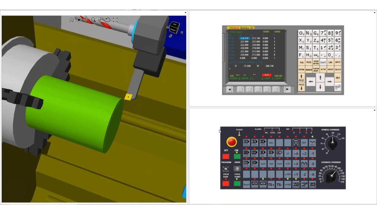
2. Running a Dry Run
Running a dry run before machining a part helps to check the accuracy of the programming. A dry run allows the CNC lathe to execute the program while it doesn’t cut the material so that the tool movements really take the intended path.
A dry run would help find wrong tool offsets, misaligned coordinates, and unexpected tool crashes from programming errors. Many CNC lathes have the option of graphical simulation for the visual representation of the tool movements so that it becomes easier to spot errors. Such early detection helps avoid any costly mistakes and damages to the machine or the workpiece.
Furthermore, the dry run will include monitoring the behavior of the toolpath so as to meet smooth operation. If there are undesired stops, sudden jerks, or incorrect speed being used by the spindle, then it means there is a programming error and needs to be fixed.
Moreover, checking feed rates and tool changes during simulation will further ensure that each operation gets executed as intended. In the event of error occurrence, analyzing the program line by line will correct the mistake.
3. Debugging Toolpaths
Even after a good dry run, your analysis of the program for optimization improves machining efficiency. Toolpath review helps to ensure every motion moves in the most direct and efficient path.
Excessive retraction of the tools, excessive rapid movements and unnecessary passes simply increase the cycle time and damage cutting tools. Thus, adjusting these paths cuts down machining time without compromising on accuracy.
Further, by tuning feed rate and spindle speed to suit your cutting characteristics of that given material, the program’s optimum performance is ensured. Thus, minor interventions here yield increased productivity and longer tool life.
Moreover, the final step of debugging means finding and correcting any last errors in the program. A careful verification of the G-codes and M-codes ensures that they let every command act according to its command. Checking for missing tool changes, wrong dwell time, or contradictory commands prevents unwarranted interruptions while machining.
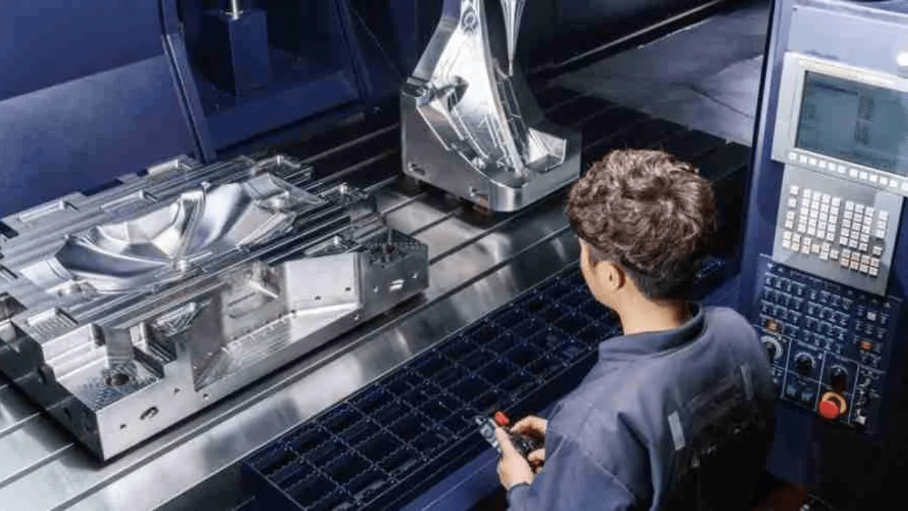
Running the Program on the CNC Lathe
· Verifying Setup Before Execution
Verify the alignment of your spindle and workpiece as well as the number of tool offsets before using.
· Starting the Machining Process Step by Step
Start with running one step at one time to ensure that all movements are correct before running the complete program.
· Monitoring Tool Wear
Keep a continuous lookout for the wear or breaking of the tool. It could be that the feed rate is to be optimized or tools are worn for replacement.
· Handling Unexpected Errors
In the event of an alarm, you should stop the machine and diagnose the problem utilizing either the CNC screen or the manual.

Quality Control of Post-Processing
· Inspecting the Finished Workpiece
Using calipers or micrometers, you should compare the overall dimension with the proposed one.
· Measuring Dimensions
The roughness gauges are helpful in verifying proper finishing.
· Adjusting Offsets
If the measurements are off slightly, you should adjust the tolerances by altering work or tool offsets to raise accuracy.
· Saving and Optimizing the Program for Future Use
You should always preserve the working programs and to optimize coding for shorter machining times.
High-end CNC Lathe Techniques for Programming
1. Use of Macros and Parametric
You can use macros and parametric programming to easily automate the repetitive task and thus make your program flexible.
Instead of writing separate codes for more or less similar operations, you can define variables and use conditionals so that the tool paths can be created dynamically. In turn, this saves programming time and checks on errors. Further, it allows rapid modification of dimensions and tolerances without the need to rewrite the whole program.
2. Using CAD CAM Software
The CAD CAM software is able to design and generate CNC programs for producing highly intricate components. It provides you with the ability to create digital models and automatically generate optimized toolpaths instead of creating every movement in the program manually. Thus, you can achieve precision and reduce human errors through this method.
3. Multi Axis Turning
A wide range of advanced geometries can be machined in a single setup using multi-axial turning. Instead of moving the workpiece to various setups, simultaneous motion with axes will allow for turning, milling, or drilling operations.
With live tool integration, milling, drilling, or tapping operations are done on the lathe. This reduces cycle time as well as further machinery processing. Hence, the use of multi-axis technology increases precision and improves productivity.
4. Automation
Automation and adaptive machining has enabled the process of production to become more efficient. Automated tool changers together with robotic loaders maintain uninterrupted processes by reducing human contact.
Common CNC Lathe Programming Mistakes and How to Avoid Them
· Incorrect Tool Offsets and Coordinate Settings
Wrong offsets lead to misalignments and errors in machining, therefore, do always check the values before cutting.
· Improper Feed and Speed Selection
Wrong settings result in poor finish, or tool wear. Thus, you should follow what the manufacturer recommends.
· Overlooking Safety Procedures
By skipping through the safety checks, you are risking injuring yourself as well as damaging the machine.
· Misinterpretation of G-Code and M-Code Functions
Deeper comprehension of each and every command helps in preventing unpredictable tool movement.
Conclusion
Precision and setting up a CNC lathe program need a lot of concentration and carefulness. Furthermore, knowledge of G-code, tooling, and quality control will help you in developing programs that are fast and free of errors.
Looking for experts in CNC lathe machine manufacturing and programming, TSINFA technicians are here to help – contact us now.