
Tsinfa is a professional supplier & manufacturer of manual lathe machine in China.
The price of manual lathe mainly depends on the rotary diameter and length between centers, as well as the weight of the workpiece. Different specifications, different prices. The specific price can be contact sales department: Give us a call at +86-15318444939, and talk to one of our expert reps. You can also fill out our: contact form.
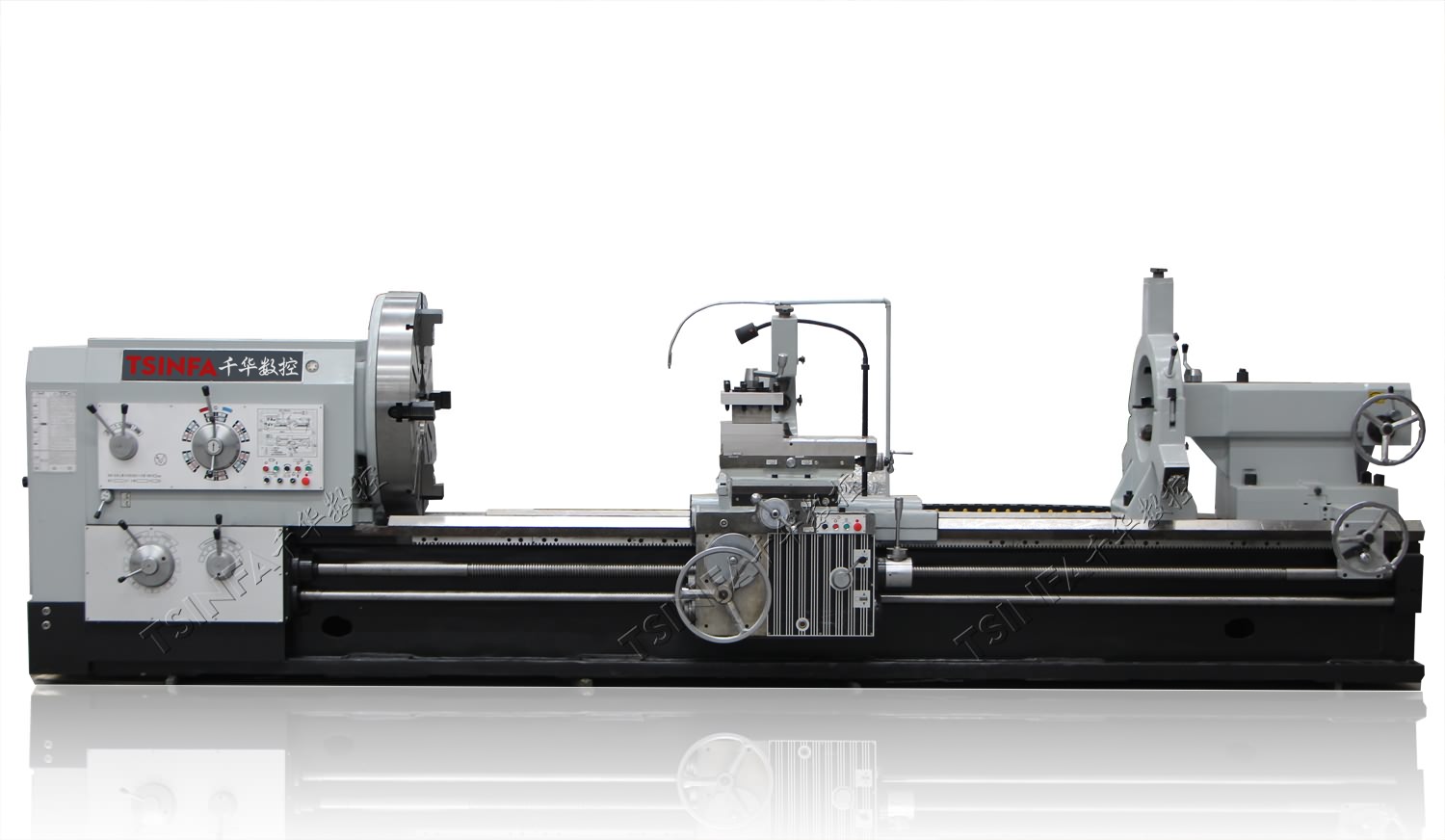
4 Meter manual lathe machine images and specification (Hot sale):

Heavy duty manual lathe machine LT6240
Swing over bed: 400mm
Spindle bore: 52/80/105mm
Distance between centers:
750/1000/1500/2000/3000/4000mm

Heavy duty manual lathe machine LT6250
Swing over bed: 500mm
Spindle bore: 52/80/105mm
Distance between centers:
750/1000/1500/2000/3000/4000mm

Heavy duty manual lathe machine LT6266
Swing over bed: 660mm
Spindle bore: 52/80/105mm
Distance between centers:
750/1000/1500/2000/3000/4000mm

Heavy duty manual lathe machine LT6280
Swing over bed: 800mm
Spindle bore: 52/80/105mm
Distance between centers:
750/1000/1500/2000/3000/4000mm

Light duty manual lathe machine LH6240C
Swing over bed: 400mm
Spindle bore: 80mm
Distance between centers:
1000/1500/2000mm

Light duty manual lathe machine LH6250C
Swing over bed:500mm
Spindle bore: 80mm
Distance between centers:
1000/1500/2000mm
Light duty conventional manual lathe machine LH6260C
Swing over bed: 600mm
Spindle bore: 80mm
Distance between centers:
1000/1500/2000mm

Medium duty manual gap type lathe machine LT6236, LT6240
Swing over bed: 360mm 400mm
Spindle bore: 52mm
Distance between centers:
750/1000/1500/2000mm

Medium duty manual lathe machine LH6251
Swing over bed: 510mm
Spindle bore: 52mm
Distance between centers:
1000/1500/2000mm

Medium duty manual lathe machine LH6260
Swing over bed: 600mm
Spindle bore: 52mm
Distance between centers:
1000/1500/2000mm

Small Manual lathe machine LH1440K
Swing over bed: 360mm
Spindle bore: 40mm
Distance between centers:
1000/1500mm
Manual heavy duty lathe machine
Swing over bed: 630-1600mm
Spindle bore: 104-520mm
Distance between centers:
1500-6000mm
Detailed description of 4 meter lathe components:
Lathe machine is generally composed of spindle box, feed box, bed, tool holder, tailstock, lead screw, cooling device, etc. Let’s see what these parts do.
- The spindle box is called the headstock, which is generally fixed on the left side of the bed. The main task of the headstock is to make the rotary turning motion transmitted by the main motor pass through a series of speed change mechanisms to make the spindle obtain the required different speeds of positive and negative steering. At the same time, the headstock will separate part of the power to transmit the motion to the feed box and provide power for the lathe thread.
The spindle in the headstock is the key part of the lathe. The spindle is a device that drives various fixtures. The spindle is hollow, and slender workpieces smaller than the spindle aperture can pass through the spindle. The end of the spindle and the tailstock are called the nose of the spindle. The chuck of the lathe and other workpiece clamping devices are fixedly installed on the nose end of the spindle and driven by the nose end of the spindle. The hole at the nose of the spindle is generally Morse taper. The model of taper varies with the model of lathe.
The spindle is supported by spindle bearings at both ends. The stability of the spindle running on the bearing directly affects the accuracy and quality of the turning workpiece. Once the rotation accuracy of the spindle is reduced, the use value of the lathe is reduced.
The change of spindle speed is also realized in the spindle box, using conveyor belt or gear.
There is also a feed reverse lever in the spindle box, also known as lead screw reverse control. Its function is very simple, which is to control the direction of the lead screw. This rotation determines the direction of feed and whether the thread on the lathe is a left-hand thread or a right-hand thread.
- The feed box, also known as the tool walking box, is equipped with a speed change device and control mechanism for feed movement. The main function is to change the pitch of the machined thread or the feed rate during motorized feed. If the speed change mechanism is adjusted, the required feed rate or pitch can be obtained, and then the motion can be transmitted to the tool holder through the lead screw or lead screw for cutting. Changing the feed rate can be divided into stepless and graded.
- Bed is an important large-scale basic component of lathe with high-precision guide rail. The bed is mainly used to support and connect various parts of the lathe, and ensure that each part has an accurate relative position during work. The rigidity and positioning of the lathe bed affect the accuracy of workpiece processing, so the structure of the lathe bed can bear the stress caused by heavy cutting. There is a guide rail on the top of the lathe bed, which is required to be very accurate. The guide rail is machined by grinding, milling and manual derusting. Worn or damaged guide rails will affect the accuracy of machined parts. Therefore, the bed and guide rail of the newly purchased lathe must be maintained.
- The chute box is composed of chute seat and bed saddle. The slide box is the control box for the feed movement of the lathe. There is a device in the slide box to change the rotary motion of the lead screw and the lead screw into the linear motion of the tool holder. The longitudinal feed movement, transverse movement and rapid movement of the tool holder are realized through the smooth screw transmission, and the tool holder is driven to make longitudinal linear movement through the lead screw, so as to turn the thread.
The bed saddle includes a gear and a feed clutch, which can transmit motion from the feed rod or from the lead screw of the cross cutter frame and the chute box.
The slide plate seat slides on the guide rail and can support the horizontal knife rest and compound knife rest.
- The tailstock is installed on the guide rail of the bed and slides on the guide rail. And move longitudinally along the guide rail to adjust its working position. The tailstock is mainly used to install the rear center to support the longer workpiece (used to support the end of the processed workpiece). It can also be installed with various cutting tools, such as drill bit, reamer, cone cutter for hole processing. The tailstock has a sliding shaft operated by a handwheel and a spindle clamping lever in the locked position. The tailstock includes upper and lower units, which can adjust the taper of the workpiece by rotating the screw in the bottom unit.
- The tool holder is composed of two layers of sliding plates (medium and small sliding plates), bed saddle and tool holder body. The tool holder is used to install the turning tool and move longitudinally, horizontally and obliquely with the motor lathetool.
- The lead screw and polished rod are used to connect the feed box and the chute box, and transmit the movement and power of the feed box to the chute box to make the chute box obtain longitudinal linear movement. The lead screw is specially used for turning various threads. When turning other surfaces of the workpiece, only polished rod is used instead of lead screw.
- The thread dial is a device fastened on the bed saddle (generally on the right) and can display an accurate half nut when cutting threads.
- The cooling device mainly pressurizes the cutting fluid in the water tank through the cooling water pump and sprays it into the cutting area to reduce the cutting temperature, wash away the cutting and lubricate the machined surface. The cooling device can improve the service life of the tool and the machining quality of the workpiece surface.