
Tsinfa is a professional supplier & manufacturer of manual lathe machine in China.
The price of manual lathe mainly depends on the rotary diameter and length between centers, as well as the weight of the workpiece. Different specifications, different prices. The specific price can be contact sales department: Give us a call at +86-15318444939, and talk to one of our expert reps. You can also fill out our: contact form.
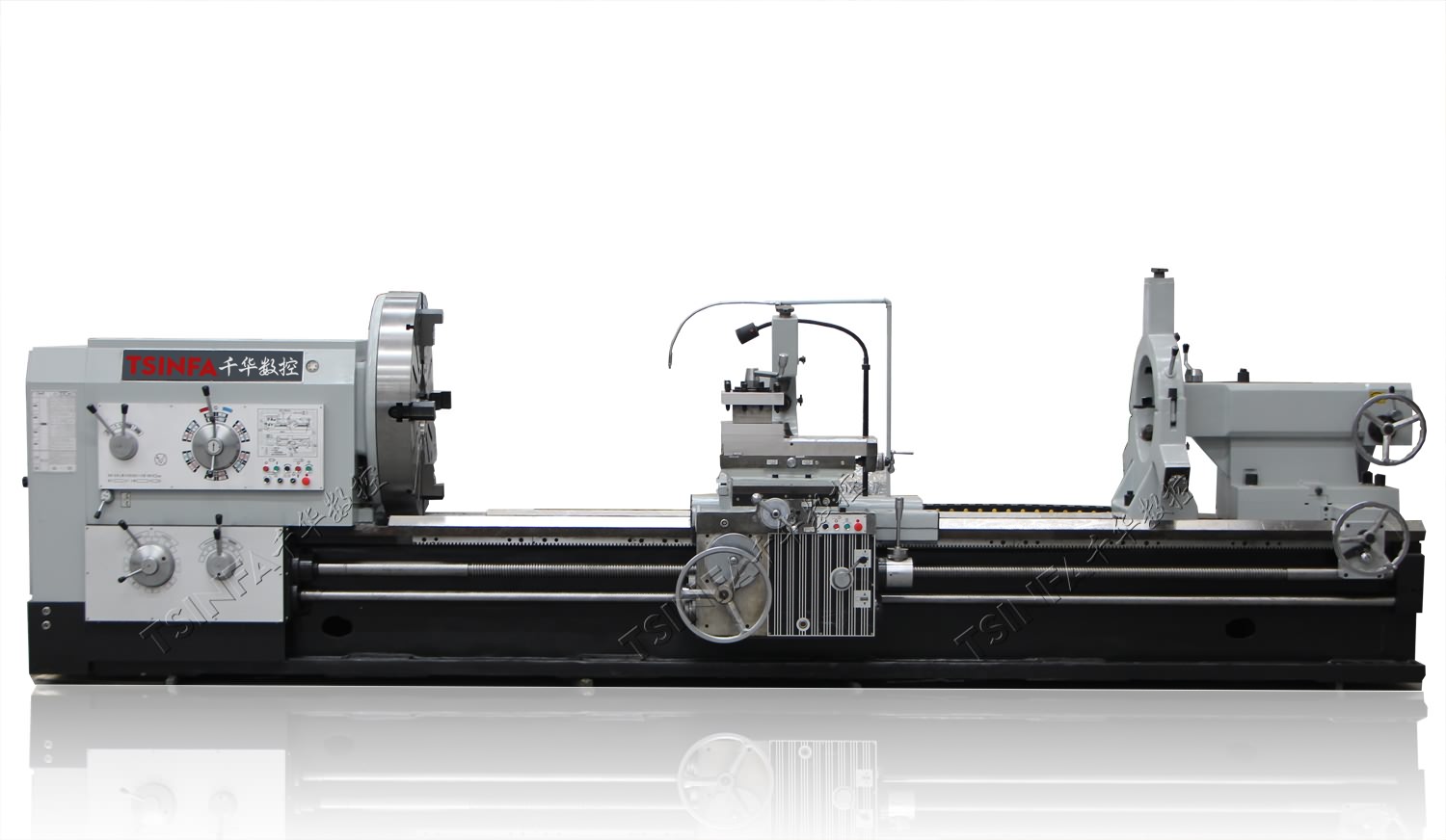
Heavy duty 6 meter lathe machine images and specification (Hot sale):

Heavy duty manual lathe machine LT6240
Swing over bed: 400mm
Spindle bore: 52/80/105mm
Distance between centers:
750/1000/1500/2000/3000/4000mm

Heavy duty manual lathe machine LT6250
Swing over bed: 500mm
Spindle bore: 52/80/105mm
Distance between centers:
750/1000/1500/2000/3000/4000mm

Heavy duty manual lathe machine LT6266
Swing over bed: 660mm
Spindle bore: 52/80/105mm
Distance between centers:
750/1000/1500/2000/3000/4000mm

Heavy duty manual lathe machine LT6280
Swing over bed: 800mm
Spindle bore: 52/80/105mm
Distance between centers:
750/1000/1500/2000/3000/4000mm

Light duty manual lathe machine LH6240C
Swing over bed: 400mm
Spindle bore: 80mm
Distance between centers:
1000/1500/2000mm

Light duty manual lathe machine LH6250C
Swing over bed:500mm
Spindle bore: 80mm
Distance between centers:
1000/1500/2000mm
Light duty conventional manual lathe machine LH6260C
Swing over bed: 600mm
Spindle bore: 80mm
Distance between centers:
1000/1500/2000mm

Medium duty manual gap type lathe machine LT6236, LT6240
Swing over bed: 360mm 400mm
Spindle bore: 52mm
Distance between centers:
750/1000/1500/2000mm

Medium duty manual lathe machine LH6251
Swing over bed: 510mm
Spindle bore: 52mm
Distance between centers:
1000/1500/2000mm

Medium duty manual lathe machine LH6260
Swing over bed: 600mm
Spindle bore: 52mm
Distance between centers:
1000/1500/2000mm

Small Manual lathe machine LH1440K
Swing over bed: 360mm
Spindle bore: 40mm
Distance between centers:
1000/1500mm
Manual heavy duty lathe machine
Swing over bed: 630-1600mm
Spindle bore: 104-520mm
Distance between centers:
1500-6000mm
How to process slender shaft?
Shaft parts with the ratio of length to diameter of the workpiece greater than 25 (i.e. L / d > 25) are called slender shafts. The shaft with the ratio of workpiece length to diameter greater than 50 and less than 100 is an ultra-fine long shaft. Shaft parts play an important role in manufacturing industry. Slender shaft is a transmission shaft part. For example, in the field of automobile, the part connecting power device and motion device plays an important part in driving power and hoisting heavy objects in the heavy machinery industry. Because the slender shaft has slender shape, poor rigidity and poor heat dissipation, it is very easy to deform in machining, which has a great impact on machining accuracy and machining quality. Under the action of turning force, centrifugal force, gravity and apical tightening force, coupled with cutting heat, the horizontally suspended slender shaft is easy to bend or even lose stability, resulting in defects such as knife shock grain, taper, waist drum shape, bamboo joint shape, triangular shape and so on. Therefore, it is necessary to solve the stress problem when turning slender shafts and ensure the dimensional accuracy. At the same time, a series of effective measures should be taken, such as reverse feed turning, with the best tool geometric parameters, cutting amount, tensioning device, shaft sleeve type tool holder, etc. This can improve the rigidity of the slender shaft and meet the machining requirements. Machining slender shaft or ultra-fine long shaft is to test the comprehensive technical level of a lathe technician. What should we do? Please refer to the following practical skills.
- Use the lathe precision self inspection to check and adjust the precision and stability of the machine tool spindle. The dial indicator can be used to detect the accuracy of chuck spindle, and keep the centerline of spindle center and tailstock center basically parallel to the full length of guide rail. Colleagues pay attention to check the vibration of each motor.
- Reverse feed turning from head to tail; Reverse feed turning is to use the pointed cutter to turn out the vacancy at the workpiece position at the head of the bed, install the tool holder, and then make cutting movement from the head of the bed to the tail of the bed. Its axial component will produce tensile force on the workpiece, making the processed part of the workpiece stretch axially, which is consistent with the heating and elongation direction of the workpiece. Compared with the forward feed, the reverse direction has better stability and vibration resistance.
- Sharp and compatible with tool parameters with certain strength; Reasonable selection of tool angle is the key to realize stable cutting.
- Selection and application of appropriate cutting parameters; Deformation can be reduced. Reduce the cutting depth as much as possible, and the increase of feed will increase the cutting thickness and cutting force. From the point of view of improving cutting efficiency, increasing feed rate is better than increasing cutting depth. Increasing the cutting speed is conducive to reducing the cutting force. With the increase of cutting speed, the cutting temperature increases, the friction between the tool and the workpiece decreases, and the force deformation of the slender shaft will decrease. However, if the cutting speed is too high, the centrifugal force will increase and destroy the stability of cutting, so the cutting speed should be controlled in a neutral range.
- Key points and application of one clip top clamping; There are two kinds of clamping for the long shaft of ordinary cars: one end of the slender shaft is clamped with a chuck, and the other end is supported by the center of the tailstock of the lathe (referred to as one clamp and one top); Grasp the jacking force of the top and feel it lightly. It is easy to retreat when retreating manually. The tightness is very light. The handle of the tailstock should be adjusted and tightened at any time to prevent the top sleeve from retreating under force and keep the position of the top unchanged. Four claw clamping is strongly recommended: use four claw chuck instead of three claw chuck, with large four claw force, strong suspension in the length direction, and it is not easy to change position when tightened in four directions; The three claw force is weak, the three directions are tightened, and the position will change overnight; Four claws shall be used, and the clamping length of the workpiece shall not exceed 60mm. Note: the clamping part is the smooth surface passed by the vehicle, which is not easy to force, and the contact point is good;
Another: both ends of the slender shaft are supported by the top (two tops); One top and two tops have great clamping force and long workpiece suspension force, but the double top tips are not as good as one top. The axial elasticity of the double top tips is insufficient. Although the positioning is accurate, the extensibility is worse. It is only suitable for shaft parts with small length diameter ratio, small machining allowance and high coaxiality requirements;
- Application of auxiliary tools such as center frame, tool heel frame and frame hoop; The center frame has two functions in the turning of slender shaft: 1. One frame is used to turn the end face, punch the center hole, grind the center hole, and make straight openings at both ends of the car; 2. The shaft body can be turned in sections, and the center frame can be directly supported in the middle of the workpiece; The length diameter ratio of this support is reduced by half, that is, the span between the shaft and the support is reduced, the workpiece stiffness is increased, and the bending deformation during shaft machining can be effectively reduced; In practical application: the transition sleeve will be used in the middle of the workpiece to turn out the frame position circle, and then move the center frame to the workpiece frame position; Fix the center frame behind the bed. When the workpiece is rotating, first make the two lower support claws evenly touch the supporting surface of the workpiece and then lock it. Then fasten the upper cover, adjust the position of the upper support claw and lock it after it is appropriate. The stress of the supporting claw is uniform and the tightness is moderate; The bearing surface is coaxial with the rotation center of the main shaft.
Generally, the tool follower is fixed on the bed saddle and has two or three supporting claws, which can follow the turning tool to offset the radial cutting force, increase the workpiece stiffness, and improve the shape accuracy and surface roughness of the long shaft; It is an indispensable accessory for machining slender shaft; The center of the heel rest, regardless of 2 claws / 3 claws, must be at the same center as the chuck and tailstock center. In order to ensure that the support head has a good contact arc surface with the outer circle of the workpiece, the cylindrical reamer or cylindrical milling cutter can be clamped on the chuck to correct the support head.
- The coolant shall be fully supplied and lubricated; Reduce cutting heat. Cutting heat during cutting will cause thermal elongation of the workpiece, resulting in bending of the long shaft due to axial extrusion. To reduce the cutting heat ratio, cutting fluid must be used. The spray should be sufficient. The liquid should cover the whole workpiece processing area and tool body. The liquid has a large flow rate, which can quickly take away a large amount of heat energy and maintain the normal temperature of the workpiece and turning tool body. This is more important. There is no water leakage in the water supply tank, Maintain good water circulation
- Processing sequence: coarse / fine / fine turning shall be separated; First rough turning, the first knife must cut the black skin. Secondly, semi finish turning: replace the fine turning tool, replace the first-order heel support claw, and repeat the procedures during rough turning for cutting. Final finishing.